Hai, pengen jadi teknisi komputer..?    gabung disini aja ...!

Kamis, 15 November 2012

Device Manager


Device Manager


Device Manager mengatur semua driver komponen hardware yang ada pada komputer.Kumpulan hardware ini yang akan mengatur hubungan hardware dengan sistem operasi agar berjalan harmonis.Pada device manager ini anda bisa melihat driver hardware mana saja yang sudah terpasang dengan baik atau belum.Cara untuk masuk tidak terlalu sulit,yaitu langkah-langkahnya sama ketika masuk system properties karena memang device manager ini terdapat di dalam system properties,hanya saja ketika sudah ada tampilan system properties seperti gambar di dibawah,kemudian klik tab Hardware kemudian pilih atau klik Device Manager,perhatikan gambar berikut,


Jika anda klik tombol [+] pada salah satu hardware,maka akan muncul daftar semua komponen hardware yang telah terpasang,apabila pada daftar terdapat logo tanda tanya,artinya hardware yang terpasang belum dikenali karena driver belum terinstall dengan benar.
read more...

System Properties

Dalam sistem operasi windows selain menggunakan perangkat lunak tambahan seperti Cpu-Z,ada cara lain untuk melihat atau mengetahui spesifikasi komputer atau spesifikasi hardware komputer kita,yaitu : 
System Properties 
Untuk masuk ke sistem properties ini caranya cukup mudah,pertama klik star-klik kanan my computer- turunkan mouse kebawah dan klik properties-akan tampak spesifikasi komputer kita.Perhatikan gambar berikut,
spesifikasi komputer


Kemudian akan tampil seperti gambar berikut,

cara mengetahui spesifikasi komputer

Spesifikasi komputer pada gambar di samping menunjukkan jenis sistem operasi 
windows xp sp 2,
jenis prosesor pentium 4 kecepatan 1,70GHz serta menunjukkan kapasitas RAM sebesar 512 MB.
read more...

BIOS


BIOS


Terdapat hampir di semua komputer.BIOS berfungsi untuk memeriksa kondisi komponen,seperti apakah komponen sudah terpasang dengan benar atau mungkin untuk memeriksa suhu,voltase, atau mungkin untuk pengaturan hardware lainnya. Ada beberapa cara untuk masuk ke menu BIOS,ada yang menggunakan tombol F2 atau dengan menekan Del.Untuk lebih jelasnya bisa dilihat pada buku manual motherboard,atau dengan melihat pada pojok kiri bawah pada tampilan awal monitor ketika komputer dinyalakan.Untuk masuk ke menu ini anda harus menekan tombol tersebut dengan timing yang tepat,yaitu pada saat komputer baru dinyalakan dan melakukan pemeriksaan hardware atau melakukan POST,segera tekan tombol F2 atau Del,tergantung perintah.Perhatikan gambar berikut,


cara masuk BIOS


Menu BIOS

Setelah tekan tombol Del,maka akan masuk ke menu BIOS,


menu BIOS
read more...

Rabu, 14 November 2012

POST code


POST code


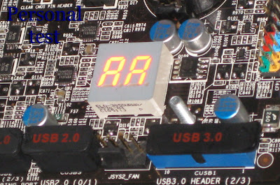
Beberapa seri Motherboard lebih memilih menggunakan post code daripada beep code karena cakupan hardware yang di deteksi lebih luas.Dengan menggunakan metode ini tidak hanya komponen utama yang bisa dideteksi akan tetapi keyboard dan mouse pun bisa dideteksi.Pada generasi terdahulu post code ini dihasilkan menggunakan kartu tersendiri yang di sebut post card.Belakangan post card ini sudah terintegrasi pada motherboard.Berikut adalah seven segmen code atau sering disebut sebagai POST (Power On Self Test). Berikut beberapa contoh Post code dari beberapa BIOS yang di ambil dari www.bioscentral.com

post code

POST code / seven segmen code pada beberapa BIOS


AMI BIOS Post Codes (After April 1990):
01NMI is disabled and the i286 register test is about to start
02i286 register test has passed
03ROM BIOS checksum test (32KB from E8000h) passed OK
04Passed keyboard controller test with and without mouse
05Chipset initialized...DMA and interrupt controller disabled
06Video system disabled and the system timer checks OK
078254 programmable interval timer initialized
08Delta counter channel 2 initialization complete
09Delta counter channel 1 initialization complete
0ADelta counter channel 0 initialization complete
0BRefresh started
0CSystem timer started
0DRefresh check OK
10Ready to start 64KB base memory test
11Address line test OK
1264KB base memory test OK
15ISA BIOS interrupt vectors initialized
17Monochrome video mode OK
18CGA color mode set OK
19Attempting to pass control to video ROM at C0000h
1AReturned from video ROM
1BShadow RAM enabled
1CDisplay memory read/write test OK
1DAlternate display memory read/write test OK
1EGlobal equipment byte set for proper
1FReady to initialize video system
20Finished setting video mode
21ROM type 27256 verified
22The power-on message is displayed
30Ready to start the virtual mode memory test
31Virtual memory mode test started
32CPU has switched to virtual mode
33Testing the memory address lines
34Testing the memory address lines
35Lower 1MB of RAM found
36Memory size computation checks OK
37Memory test in progress
38Memory below 1MB is initialized
39Memory above 1MB is initialized
3AMemory size is displayed
3BReady to test the lower 1MB of RAM
3CMemory test of lower 1MB OK
3DMemory test above 1MB OK
3EReady to shutdown for real-mode testing
3FShutdown Ok - now in real mode
40Cache memory now on...Ready to disable gate A 20
41A20 line disabled successfully
42i486 internal cache turned on
43Ready to start DMA controller test
50DMA page register test OK
51Starting DMA controller 1 register test
52DMA controller 1 test passed, starting DMA controller 2 register test
53DMA controller 2 test passed
54Ready to test latch on DMA controller 1 and 2
55DMA controller 1 and 2 latch test OK
56DMA controller 1 and 2 configured OK
578259 programmable interrupt controller initialized Ok
70Start of keyboard test
71Keyboard controller OK
72Keyboard test OK...Starting mouse interface test
73Keyboard and mouse global initialization OK
74Display setup prompt.. Floppy setup ready to start
75Floppy controller setup OK
76hard disk setup ready to start
77Hard disk controller setup OK
79Ready to initialize timer data
7ATimer data area initialized
7BCMOS battery verified OK
7ECMOS memory size updated
7FEnable setup routine if <Delete> is pressed
80Send control to adapter ROM at C800h to DE00h
81Return from adapter ROM
82Printer data initialization is OK
83RS-232 data initialization is OK
8480x87 check and test OK
85Display any soft error message
86Give control to ROM at E0000h
A0Program the cache SRAM
A1Check for external cache
A2initialize EISA adapter card slots
A3Test extended NMI in EISA system
00Call the INT19 boot loader


AMI 2.2 BIOS:
00Flag test; Testing of the CPU
03Register test
06Chipset test; System hardware initialized
09BIOS checksum tested
0CPage register tested
0F8254 timer tested
12Memory refresh initialization
158237 DMA controllers tested
188237 DMA initialization
1B8259 PIC initialization
1E8259 PIC chips tested
21Memory refresh tested
24Base 64 address tested
27Base 64 memory tested
2A8742 keyboard tested
2DMC146818 RTC/CMOS
30Protected mode started
33Memory sizing test
36First protected mode test passed
39First protected mode test failed
3CCPU speed calculation
3FRead 8742 hardware switches
42Initialize interrupt vector area
45Verify CMOS configuration
48Test and initialize video system
4BUnexpected interrupt tested
4EStart second protected mode test
51Verify LDT instruction
54Verify TR instruction
57Verify LSL instruction
5AVerify LAR instruction
5DVerify VERR instruction
60Address line A20 test
63Unexpected exception tested
66Start third protected mode test
69Address line tested
6AScan DDNIL bits for null pattern
6CSystem memory tested
6FShadow memory tested
72Extended memory tested
75Verify memory configuration
78Display CMOS error messages
7BCopy system BIOS shadow memory
7E8254 clock tested
81MC146818 RTC tested
84Keyboard test
87Determine keyboard type
8AStuck key test
8DInitialize hardware Interrupt vectors
90Math co-processor tested
93Determine COM ports available
96Determine LPT ports available
99Initialize BIOS data area
9CFixed/floppy controller tested
9FFloppy disk tested
A2Fixed disk tested
A5External ROM screen; Check for external ROM's
A8System key lock test
AEF1 error message test
AFSystem boot initialization
B1Call to Interrupt 19 boot loader
read more...

Selasa, 13 November 2012

Beep Code

Beep Code


Merupakan salah satu alat bantu standar yang ada pada komputer modern.Keberadaannya ini ditunjang dengan adanya perangkat buzzer untuk menghasilkan suara standar.Beep Code berfungsi untuk mengindikasikan adanya kesalahan fatal yang membuat sistem tidak dapat melakukan proses booting.Kesalahan ini mencakup beberapa hal mulai dari prosesor,memori,harddisk,timer,dll.


beep code


Berikut beberapa contoh Beep Code yang di ambil dari http://www.computerhope.com/beep.htm.

AMI BIOS beep codes
Below are the AMI BIOS Beep codes that can occur. However, because of the wide variety of different computer manufacturers with this BIOS, the beep codes may vary.

Beep CodeDescriptions
1 shortDRAM refresh failure
2 shortParity circuit failure
3 shortBase 64K RAM failure
4 shortSystem timer failure
5 shortProcess failure
6 shortKeyboard controller Gate A20 error
7 shortVirtual mode exception error
8 shortDisplay memory Read/Write test failure
9 shortROM BIOS checksum failure
10 shortCMOS shutdown Read/Write error
11 shortCache Memory error
1 long, 3 shortConventional/Extended memory failure
1 long, 8 shortDisplay/Retrace test failed


AWARD BIOS beep codes
Below are Award BIOS Beep codes that can occur. However, because of the wide variety of different computer manufacturers with this BIOS, the beep codes may vary.

Beep CodeDescription
1 long, 2 shortIndicates a video error has occurred and the BIOS cannot initialize the video screen to display any additional information
Any other beep(s)RAM problem.
If any other correctable hardware issues, the BIOS will display a message.

IBM BIOS beep codes
Below are general IBM BIOS Beep codes that can occur. However, because of the wide variety of models shipping with this BIOS, the beep codes may vary.

Beep CodeDescription
No BeepsNo Power, Loose Card, or Short.
1 Short BeepNormal POST, computer is ok.
2 Short BeepPOST error, review screen for error code.
Continuous BeepNo Power, Loose Card, or Short.
Repeating Short BeepNo Power, Loose Card, or Short.
One Long and one Short BeepMotherboard issue.
One Long and Two Short BeepsVideo (Mono/CGA Display Circuitry) issue.
One Long and Three Short Beeps.Video (EGA) Display Circuitry.
Three Long BeepsKeyboard or Keyboard card error.
One Beep, Blank or Incorrect DisplayVideo Display Circuitry.

Macintosh startup tones

TonesError
Error Tone. (two sets of different tones)Problem with logic board or SCSI bus.
Startup tone, drive spins, no videoProblem with video controller.
Powers on, no tone.Logic board problem.
High Tone, four higher tones.Problem with SIMM.

Phoenix BIOS beep codes
Below are the beep codes for Phoenix BIOS Q3.07 OR 4.X

Beep CodeDescription and what to check
1-1-1-3Verify Real Mode.
1-1-2-1Get CPU type.
1-1-2-3Initialize system hardware.
1-1-3-1Initialize chipset registers with initial POST values.
1-1-3-2Set in POST flag.
1-1-3-3Initialize CPU registers.
1-1-4-1Initialize cache to initial POST values.
1-1-4-3Initialize I/O.
1-2-1-1Initialize Power Management.
1-2-1-2Load alternate registers with initial POST values.
1-2-1-3Jump to UserPatch0.
1-2-2-1Initialize keyboard controller.
1-2-2-3BIOS ROM checksum.
1-2-3-18254 timer initialization.
1-2-3-38237 DMA controller initialization.
1-2-4-1Reset Programmable Interrupt Controller.
1-3-1-1Test DRAM refresh.
1-3-1-3Test 8742 Keyboard Controller.
1-3-2-1Set ES segment to register to 4 GB.
1-3-3-128 Autosize DRAM.
1-3-3-3Clear 512K base RAM.
1-3-4-1Test 512 base address lines.
1-3-4-3Test 512K base memory.
1-4-1-3Test CPU bus-clock frequency.
1-4-2-4Reinitialize the chipset.
1-4-3-1Shadow system BIOS ROM.
1-4-3-2Reinitialize the cache.
1-4-3-3Autosize cache.
1-4-4-1Configure advanced chipset registers.
1-4-4-2Load alternate registers with CMOS values.
2-1-1-1Set Initial CPU speed.
2-1-1-3Initialize interrupt vectors.
2-1-2-1Initialize BIOS interrupts.
2-1-2-3Check ROM copyright notice.
2-1-2-4Initialize manager for PCI Options ROMs.
2-1-3-1Check video configuration against CMOS.
2-1-3-2Initialize PCI bus and devices.
2-1-3-3Initialize all video adapters in system.
2-1-4-1Shadow video BIOS ROM.
2-1-4-3Display copyright notice.
2-2-1-1Display CPU type and speed.
2-2-1-3Test keyboard.
2-2-2-1Set key click if enabled.
2-2-2-356 Enable keyboard.
2-2-3-1Test for unexpected interrupts.
2-2-3-3Display prompt Press F2 to enter SETUP.
2-2-4-1Test RAM between 512 and 640k.
2-3-1-1Test expanded memory.
2-3-1-3Test extended memory address lines.
2-3-2-1Jump to UserPatch1.
2-3-2-3Configure advanced cache registers.
2-3-3-1Enable external and CPU caches.
2-3-3-3Display external cache size.
2-3-4-1Display shadow message.
2-3-4-3Display non-disposable segments.
2-4-1-1Display error messages.
2-4-1-3Check for configuration errors.
2-4-2-1Test real-time clock.
2-4-2-3Check for keyboard errors
2-4-4-1Set up hardware interrupts vectors.
2-4-4-3Test coprocessor if present.
3-1-1-1Disable onboard I/O ports.
3-1-1-3Detect and install external RS232 ports.
3-1-2-1Detect and install external parallel ports.
3-1-2-3Re-initialize onboard I/O ports.
3-1-3-1Initialize BIOS Data Area.
3-1-3-3Initialize Extended BIOS Data Area.
3-1-4-1Initialize floppy controller.
3-2-1-1Initialize hard-disk controller.
3-2-1-2Initialize local-bus hard-disk controller.
3-2-1-3Jump to UserPatch2.
3-2-2-1Disable A20 address line.
3-2-2-3Clear huge ES segment register.
3-2-3-1Search for option ROMs.
3-2-3-3Shadow option ROMs.
3-2-4-1Set up Power Management.
3-2-4-3Enable hardware interrupts.
3-3-1-1Set time of day.
3-3-1-3Check key lock.
3-3-3-1Erase F2 prompt.
3-3-3-3Scan for F2 key stroke.
3-3-4-1Enter SETUP.
3-3-4-3Clear in-POST flag.
3-4-1-1Check for errors
3-4-1-3POST done--prepare to boot operating system.
3-4-2-1One beep.
3-4-2-3Check password (optional).
3-4-3-1Clear global descriptor table.
3-4-4-1Clear parity checkers.
3-4-4-3Clear screen (optional).
3-4-4-4Check virus and backup reminders.
4-1-1-1Try to boot with INT 19.
4-2-1-1Interrupt handler error.
4-2-1-3Unknown interrupt error.
4-2-2-1Pending interrupt error.
4-2-2-3Initialize option ROM error.
4-2-3-1Shutdown error.
4-2-3-3Extended Block Move.
4-2-4-1Shutdown 10 error.
4-3-1-3Initialize the chipset.
4-3-1-4Initialize refresh counter.
4-3-2-1Check for Forced Flash.
4-3-2-2Check HW status of ROM.
4-3-2-3BIOS ROM is OK.
4-3-2-4Do a complete RAM test.
4-3-3-1Do OEM initialization.
4-3-3-2Initialize interrupt controller.
4-3-3-3Read in bootstrap code.
4-3-3-4Initialize all vectors.
4-3-4-1Boot the Flash program.
4-3-4-2Initialize the boot device.
4-3-4-3Boot code was read OK.
read more...

Alat Service Komputer

Alat Service Komputer


Sangat penting kaitannya dengan perbaikan atau service komputer,terdiri dari alat-alat sederhana yang sering di jumpai,sehingga mudah bagi anda yang ingin melakukan service komputer secara mandiri.


1.Obeng Plus
Obeng plus bergagang karet dengan batang yang cukup panjang dengan kepala berjenis magnetik.
Alat Service Komputer


2.Tang

alat-alat service


3.Kuas Pembersih
Untuk membersihkan debu atau kotoran yang menempel pada perangkat keras komputer.Karena debu atau kotoran juga merupakan salah satu sebab kerusakan pada komputer,jadi alat ini juga di perlukan.


4.Amplas
Untuk membersihkan karat pada casing,untuk memaksimalkankerja heatsink pendingin agar permukaannya lebih rata.Dalam hal ini gunakan amplas yang sangat halus.


5.AVO Meter
Untuk mengecek arus atau tegangan yang keluar atau masuk dari power supply.


6.Alkohol
Untuk membersihkanperangkat seperti interkoneksi(lapisan emas) kartu grafis dan memori,juga dapat untuk membersihkan processor,terkadang cairan benzoat menjadi cairan pengganti alkohol.

7.Klip
Digunakan untuk mengeluarkan CD dari Drive dengan menggunakan lubang emergency.


8.Manual Book
Pada buku manual terdapat informasi spesifikasi dan beberapa cara yang dibutuhkan untuk melakukan pemasangan,untuk mengetahui posisi jumper pada motherboard.

9.Perangkat lunak pendukung

CPU-Z
Memiliki fungsi untuk mengetahui semua informasi hardware seperti processor,motherboard,dan memory.Cari saja di www.cpuid.com


ATITools
Software untuk mengoptimalkan kerja kartu grafis,dengan software ini anda bisa melakukan pengaturan pada Core atau Memory.Jangan berlebihan memberi nilai Core atau Memory,pengaturan yang terlalu tinggi(melebihi kemampuan kartu grafis) bisa menyebabkan kartu grafis anda tidak bekerja semestinya.


read more...

Belajar Service Komputer

Belajar Service Komputer


Dalam melakukan perbaikan komputer atau service komputer ada beberapa langkah yang harus dilakukan serta alat-alat service komputer yang harus disiapkan.


Menganalisa Kerusakan Komputer.

Sebelum melakukan otak-atik dan service komputer,hal pertama yang harus dilakukan adalah menganalisa kerusakan pada komputer,hal ini sangat penting supaya kita bisa fokus pada pokok atau inti permasalahan.Dalam melakukan analisa cobalah melakukannya dengan cara mengecek satu persatu komponen,misalnya kita coba cek RAM tanpa mengotak-atik komponen yang lain,jika ternyata setelah di cek RAM nya masalah belum teratasi maka pasang kembali RAM dan mulai lakukan pengecekan pada komponen yang lain dengan langkah yang sama,yaitu satu per satu,jangan langsung di otak atik semua secara bersamaan.

Siapkan Alat Service Komputer.

Setelah melakukan analisa kerusakan pada komputer langkah selanjutnya adalah mempersiapkan alat service komputer. Alat sederhana yang harus disiapkan seperti,obeng plus untuk membuka baut,kuas untuk membersihkan hardware komputer.Untuk alat yang harus disiapkan ini adalah tergantung hasil dari analisa kerusakan,ketika hasil analisa ternyata komputer hanya perlu dibersihkan RAM atau hardware lainnya maka obeng plus dan kuas atau alat pembersih lainnya itu sudah cukup.

Cabut kabel Power Komputer

Jangan lupa untuk mencabut kabel power sebelum memulai service komputer. Jangan lupa gunakan pengaman listrik statis,dengan memakai gelang anti listrik statis atau juga bisa juga dengan cara berikut,letakkan tangan anda di tanah atau lepaskan alas kaki untuk sementara waktu agar listrik statis terbuang dari tubuh.

Catatlah semua langkah-langkah yang telah anda lakukan dari awal,mulai dari permasalahan yang di hadapi apa,kemudian analisa awal komponen apa yang di periksa,kemudian langkah apa saja yang di lakukan untuk mengadakan perbaikan pada komponen hasil analisa,alat apa saja yang digunakan,kemudian terakhir adalah bagaimana hasilnya.


Lakukan Final Cek

Lakukan pengecekan ulang dan pastikan semua komponen telah terpasang dengan benar.Bila ternyata masalah belum teratasi,berarti analisa anda salah,lakukan langkah-langkah di atas sampai anda berhasil mengatasi masalah pada komputer anda atau bertanyalah kepada orang yang sudah ahli,tanyakan permasalahan pada komputer anda dan langkah-langkah apa saja yang harus dilakukan untuk memperbaiki permasalahan tersebut,kemudian kerjakan sendiri,karena hal itu bisa menambah pengalaman dan jam terbang anda.

read more...